Adventure 2a: Light an LED
Goal
Understand how Light-Emitting Diodes (LEDs) work. Simulate a circuit where we use a voltage source to light an LED. Then, build it on a breadboard, to light the LED.
Simulate circuit
Watch this short video on how LEDs work.
Note your LEDs specify a voltage range, e.g., \(2.0V - 2.5V\), and a current specification, e.g., \(20mA\). This means the LED requires the voltage across its terminals to be within \(2.0V - 2.5V\), and the current flowing through it will be \(20mA\) when the voltage is at this range.
How much voltage does our voltage source supply? Why can’t we just connect the LED directly to our voltage source?
Answer
Our voltage source supplies about \(5V\). The LED requires \(2.0V - 2.5V\) so we cannot connect it to the voltage source directly. Doing so would destroy the LED.
Warning
Never connect the LED directly to a voltage source outside its voltage range. Watch this video by Ben Eater where he demonstrates how too much voltage destroys the LED.
Remember how connecting multiple resistors in series in Adventure 1a: Equivalent resistance: Resistors in series reduces the current that flows through the circuit. Also note connecting multiple resistors in series divides the input voltage between them. How can we limit the voltage across the LED and the amount of current that flows through the LED?
Answer
We will connect a resistor in series with the LED, to limit the voltage across its terminals.
Open Circuit Simulator and load the circuit from Adventure 0: Ohm’s Law. Here is an example of the finished circuit: Circuit - Ohm’s law.
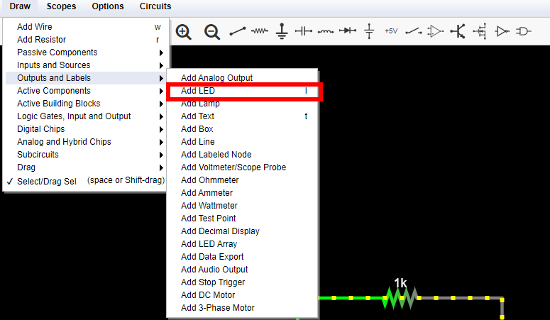
Click Draw –> Outputs and Labels –> Add LED to add a new LED to your circuit. Here is a screenshot to help you find the menu entry, also note you can use keyboard shortcut
l:
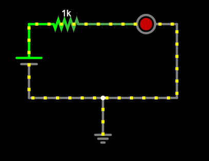
Add the LED in series with the existing resistor in your circuit. Note the LED has specific polarity. One terminal is the positive terminal, or anode (+), one terminal is the negative terminal, or cathode (-). The LED is a diode, so it allows current to flow in a single direction, from the anode to the cathode. The symbol for a diode look like an arrow pointing in the direction of current flow:
After adding the LED, your circuit should look like this:

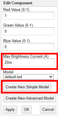
Double click the LED and edit it to specify the right value for Max Brightness Current according to your own LEDs, for example \(20mA\). Then, click
Create New Simple Modeland change Forward Voltage to match the maximum voltage of your LED, for example \(2.5V\).
Ensure the resistor is \(1kΩ\). Hover your mouse over the LED. How much current flows through it, how much is the voltage drop around it? Is the current and voltage inside the right range for your LED? Does it produce a bright light?
Answer
The current is lower than it should, \(3.1mA\) and the voltage is outside the right range, at \(1.88V\). The LED only produces a dim light.
Edit the resistor and play with different resistance values. What happens to the current that flows through the circuit depending on the resistance? What resistor should you use for your LED?
Answer
Increasing the resistance decreases the current even more. Decreasing the resistance increases the current and the voltage across the LED. A good value seems is \(150Ω\). In this case, the current is \(19.5mA\) and the voltage across the LED is \(2.07V\), both within range. So, we can use a \(150Ω\) resistor.
If you would like some help with creating the circuit, see below.
- class:
dropdown Here is an example of the finished circuit: Circuit - Light an LED.
We found the right resistor to use by trying different resistance values. Can we calculate the right resistance? We know the operating parameters of the LED: voltage must be \(2.0 - 2.5V\), in which case the current is \(20mA\). Can you calculate the right resistance using Ohm’s law?
Tip
An LED itself does not follow Ohm’s law. It is not a resistor, we cannot use Ohm’s law on it. But we can use Ohm’s low on the resistor we connect in series with it, to limit its current. We know the current, and we know how much we want the voltage across the LED to be. In Adventure 1a: Equivalent resistance: Resistors in series we saw that connecting two resistors in series divides the input voltage between them. This holds for all kinds of components: the voltage across the resistor and the voltage across the LED add up to the input voltage.
- class:
hint
- class:
dropdown In Adventure 1a: Equivalent resistance: Resistors in series we saw that connecting two resistors in series divides the voltage between them. Let’s call \(V_R\) the voltage across the resistor, \(V_L\) the voltage across the LED, and \(V_T\) the total voltage:
\[ V_T = V_R + V_L \]
We know we want the voltage on the LED to be between \(2.0V - 2.5V\), so let’s choose \(V_L = 2.0V\) to be on the safe side. We also know \(V_T = 5V\), because this is our power supply. In this case the voltage across the resistor will be:
\[ V_R = V_T - V_L = 5V - 2V = 3V \]To calculate the resistance we need, we also need to know the current we want to flow through the resistor. We know the current flowing through the LED should be 20mA, and our components are connected in series, so the current flowing through the resistor is \(I_R = 20mA\).
We can know use Ohm’s law to compute the resistance:
\[ R = {V_R \over I_R} = {3V \over 20mA} = {3V \over {20 \cdot 10^{-3}mA}} = {3000V \over 20A} = 150Ω\].This agrees with the results of our simulation, so let’s build it!
Build circuit
Grab your breadboard! Start from the original circuit you had built for Adventure 0: Ohm’s Law:
Make sure your circuit is powered off, disconnect the DC power cable from the round DC power plug.
Use an \(150Ω\) resistor in series with the LED.
Add your LED in series with the resistor. Note the long leg is the anode, (+), so place it towards VCC, and the short leg is the cathode, (-), so place it towards GND.
Danger
Do not connect the LED directly to VCC and GND, you have to include a current-limiting resistor in between, to protect the LED.
Confirm everything looks good, then power on your circuit, your LED should shine bright! If it doesn’t, power off your circuit immediately, and go over your circuit again, to ensure everything looks good.
Connect your multimeter in series and measure the current flowing around the circuit, \(I\). Write down this current. It should be close to the expected value. Example measurement: \(I = 20.4mA\).
How much do you expect the voltage drop around the resistor to be? Use your multimeter to measure it. Write down your measurement, and compare it with what you expected.
Answer
We expect the voltage drop to be \(V = IR \approx 3V\), based on Ohm’s law and our chosen resistance. Example measurement: \(3.02V\). This is very close to our expected value.
Measure the supply voltage. How much do you expect the voltage drop across the LED to be?
Answer
It should be the difference between the supply voltage and the voltage measured drop across the resistor, for example \(5.11V - 3.02V\) = \(2.09V\), which is in the right range for our LED.
Does it make a difference if the resistor sits between VCC and the anode of the LED, or if it sits between the cathode of the LED and GND?
Answer
No, because the current flowing through the LED and its voltage is the same.
Add a momentary switch (push button) in series with the LED. Use the multimeter to find out what each pin does, set it to “Ω - 🎵” mode. Push the button to turn on the LED at will.
Replace the momentary switch a small “Single Pole - Double Throw” (SPDT) switch, in series with the LED. Use the multimeter to find out what each pin does, set it to “Ω - 🎵” mode. Flip the switch to turn the LED on and off at will.
Celebrate
Congratulations! You’ve simulated and built a circuit to light an LED, using a resistor to limit the current that flows through it.
Here are more challenges to explore, as you prepare to embark on your next adventure.
The switch is a double throw switch. Design, simulate, and build a circuit with two LEDs: One of the two LEDs should always be on, and you can choose which one of the two LEDs to light based on the position of the switch.
Important
Pay attention to the polarity of the LEDs.
Here are more resources to explore:
